Internal Scanning
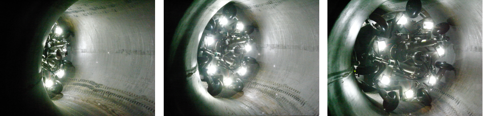
Buried pipe inspection
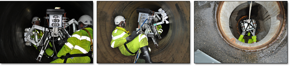
For the inspection of buried pipework in industrial plants like tank to tank connections in refineries and storage plants, street, railway or river crossings, cooling water pipes in nuclear and thermal power plants, pressure pipes in electro-hydraulic power plants, etc… testing systems with particular features are required. From the design those pipeworks generally are not foreseen to be piggable. Therefore following situations can occur:
- a launching/receiving station is not existing. Therefore for insertion of the tool only a short pipe section or an armature can be removed.
- in many cases access into the pipe is possible only from one end. The tool must allow bi-directional movement.
- the pipework has short bends with radiuses down to 1.5 x D.
- in many cases the pipes are coated on the inner surface by rubber, GRP or concrete.
- a comprehensive cleaning prior to the inspection is not possible. The surface can be covered by residue from the product, scaling, etc..
- the pipes can only be tested without medium. The use of water or other coupling liquids in many cases is unwanted.
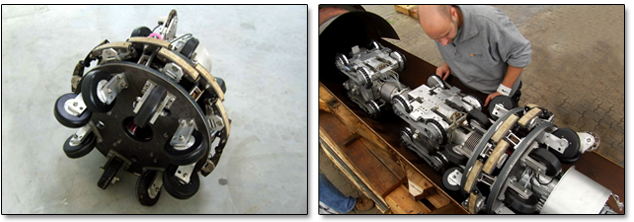
Kontrolltechnik GmbH has developed the SLOFEC® umbilical pipe inspection tools, type PLM and type PLS. Both scanner types have a modular design, which can easily be adapted to the situation on site. The design features of the SLOFEC® pipe inspection tools and advantages of the SLOFEC® technique are as follows:
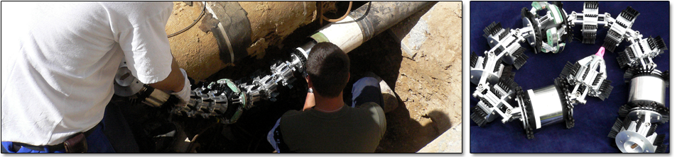
- The SLOFEC® pipe inspection tool consists of single modules, which are connected by flexible joints. Each module is minimized in length allowing the tool to pass narrow bends.
- The modules of the tools can be assembled on site. Even if due to limited access only modules or parts of the tool can be inserted in the pipe in many cases the assembly inside the pipe is possible.
- Each SLOFEC® pipe inspection tool can be moved bi-directionally using a crawler system or pulled through the pipe by means of a winch.
- The SLOFEC® pipe inspection tool type PLS has retractable centering devices and a retractable sensor head to pass sections with a reduced diameter.
- The SLOFEC® technique is very sensitive to local corrosional attack.
- The SLOFEC® technique can test through non-conductive coatings up to 10 mm thickness.
- The SLOFEC® technique needs no coupling liquid.
- The SSLOFEC® technique is insensitive to residues.
Technical Information SLOFEC® Internal Pipe Scanner
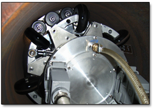
Type PLM
The SLOFEC® Internal Pipe Scanner Type PLM is designed as a drive-through unit either connected to a crawler system or pulled by a winch. The sensors are spring loaded and arranged between the poles of the magnetization unit. The complete sensor head is guided on wheels for low friction and bi-directional operation. The advantage of PLM type scanner is the applicability for the inspection of pipes with relatively small diameters and the rather high inspection speed.
PLM type scanner
Technical features
|
pipe diameter range pipe wall thickness range max. coating thickness max. inspection length sensor coverage minimal passable bend radius |
max. data acquisition speed sensor head weight drive propulsion system max. diameter reduction determination of the axial signal position not possible in the current models |
Advantages and limitations of the SLOFEC® Pipe Testing Unit
Type PLM
Advantages:
- 360° coverage at axial movement
- high testing speed
- passage of small bends
- inspection of the bend zone is possible
Limitations:
- high unit weight for big diameter tools
- relatively small resolution in circumferential direction
- butt welds and an area of approx. 50 mm to either side of butt welds remain untested due to the noise signal from the weld
- restrictions in the passage of sections with reduced Diameter
Technical Information SLOFEC® Internal Pipe Scanner
Type PLS
 The SLOFEC® Internal Pipe Scanner Type PLS is a scanner unit with a rotating sensor head. The scanner unit is designed to be connected either to a crawler system or pulled by a winch. For data acquisition the scanner will be positioned by the crawler or winch in axial direction. In position the sensor head will be radially pressed against the pipe wall by means of pneumatic or hydraulic cylinders and moved in circumferential direction. After completion of a complete circumferential scan, the sensor heads will be retracted and the complete pipe testing unit will be moved one sensor head width in axial direction. In this position the data acquisition procedure will be started again. The scanning procedure is fully automated to reach reasonable inspection velocities.
The complete sensor head is guided on wheels for low friction and bi-directional operation. The centering devices can be expanded and folded to pass sections with reduced diameter. The advantage of PLS type scanner type is reduced weight compared to the PLM type scanner, especially for bigger diameters, the higher resolution and the reduced dead zones at butt welds or pipe connections.
PLS type scanner
Technical features
|
pipe diameter range pipe wall thickness range max. coating thickness max. inspection length sensor coverage minimal passable bend radius |
max. data acquisition speed sensor head weight drive propulsion system determination of the axial signal position for determination of circumferential signal position a gravity sensor and odometer wheel is used. |
Advantages and limitations of the SLOFEC® Pipe Testing Unit
Type PLS
Advantages:
- small unit weight even for big diameter tools
- high resolution in circumferential and axial direction
- no dead zones at either side of butt welds
- for even shaped butt welds testing of the weld itself is possible
- less restriction in the passage of diameter reductions compared to the PLM type scanner
Limitations:
- reduced testing speed compared to the PLM type scanner
- passage of small bends may not be possible (mainly for small pipe diameter)
- inspection of the bend zones is limited
Technical Information SLOFEC® Internal Pipe Scanner
Type PLS-M
The SLOFEC® Internal Pipe Scanner Type PLS-M has the same working principle as the PLS type tool. The difference is, that PLS-M unit is designed for the inspection of pipes, where personal access inside the pipe is possible or where the unit can be pulled by a winch. The operation in combination with a crawler system is not planned in this design.
 PLS-M type scanner
Technical features
|
pipe diameter range pipe wall thickness range max. coating thickness max. inspection length sensor coverage minimal passable bend radius |
max. data acquisition speed total scanner weight drive propulsion system max. diameter reduction determination of the axial signal position determination of the circumferential signal position |
Advantages and limitations of the SLOFEC® Pipe Testing Unit
Type PLS-M
Advantages:
- small unit weight even for big diameter tools
- high resolution in circumferential and axial direction
- no dead zones at either side of butt welds
- for even shaped butt welds testing of the weld itself is possible
- less restrictions in the passage of diameter reductions compared to the PLM type scanner
- installation through manholes is possible
Limitations:
- reduced testing speed compared to the PLM type scanner
- passage of small bends may not be possible (mainly for small pipe diameter)
- inspection of the bend zones is limited
Technical Information Internal Pipe Scanner
Type PLM-S.MB and PLM-S.RF
The Internal Pipe Scanner Type PLM-S.MB and PLM-S.RF are designed as drive-through probes for the inspection of small diameter pipes. The scanners are either pulled through a pipe section by a winch or by the signal cable.
In both types the sensors are spring loaded and arranged between the poles of the magnetization unit (Type PLM-S.MB) respectively the transmitter coils (Type PLM-S.RF) to pass sections with diameter reductions.
The advantage of PLM-S.MB and PLM-S.RF type scanner are the applicability for the inspection of pipes with relatively small diameters and the rather high inspection speed.
 PLM-S.RF type scanner PLM-S.RF type scanner
Technical features
|
pipe diameter range pipe wall thickness range max. coating thickness max. inspection length sensor coverage minimal passable bend radius |
max. data acquisition speed sensor head weight drive propulsion system max. diameter reduction determination of the axial signal position not possible |
Advantages and limitations of the Internal Pipe Scanner
Type PLM-S.MB and PLM-S.RF
Advantages:
- 360° coverage at axial movement
- high testing speed
- inspection of the bend zone is possible
Limitations:
- relatively small resolution in circumferential direction (depending on pipe diameter)
- butt welds and an area of approx. 50mm to either side of butt welds remain untested due to the noise signal from the weld
- restrictions in the passage of sections with reduced diameter
Result Documentation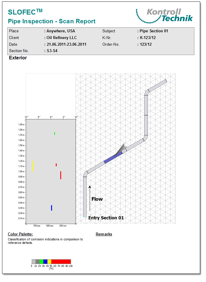
Section report
The result documentation consists of a colored pipe section reports and a feature list. In the “Pipe Scan Report” reports for each tested pipe section wall thickness reductions will be shown in a 2D-scan color image, where the defect depth corresponds to a defined color.
Example for a pipe section report:
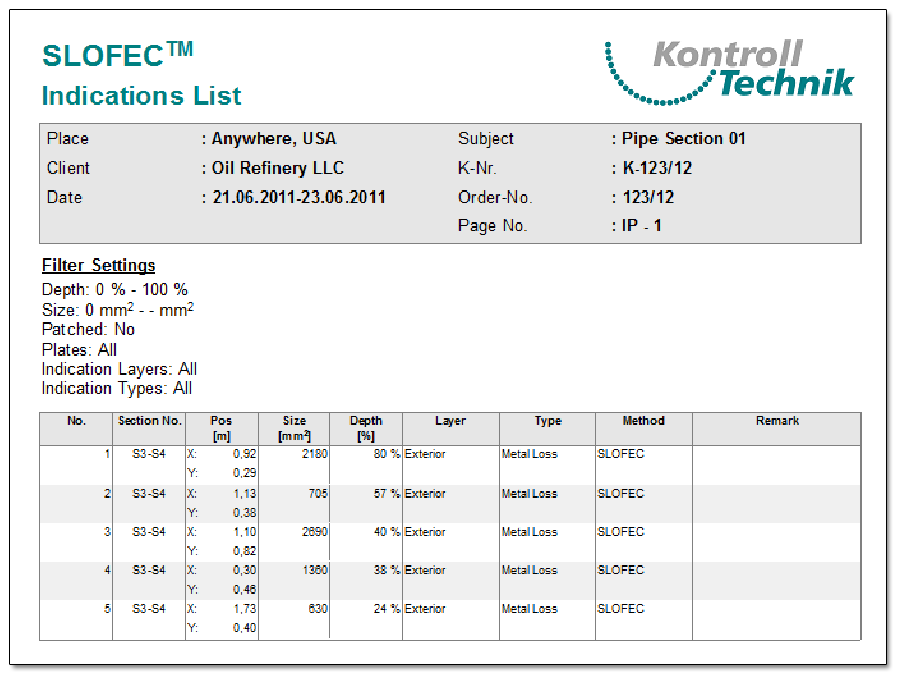
Indication List
The “Indication List” shows the evaluated depth, position, size and identification as internal or external defect.
Example for an indication List: